
Today came in a new batch of PCBs from DirtyPCB.com, of which one is a new revision of the BlackMagicProbe. This revision is almost the same except it has a polyfuse in its powersupply to the target, a dedicated voltage regulator instead of P-FET, its programming header on the 90 degree on the side and a jumper for entering DFU mode. All this goodness is contained in less 5×2 cm PCB space, so quite a bit of PCB estate is left for other purposes and I used panelizing in EAGLE to try another brainfart of mine.
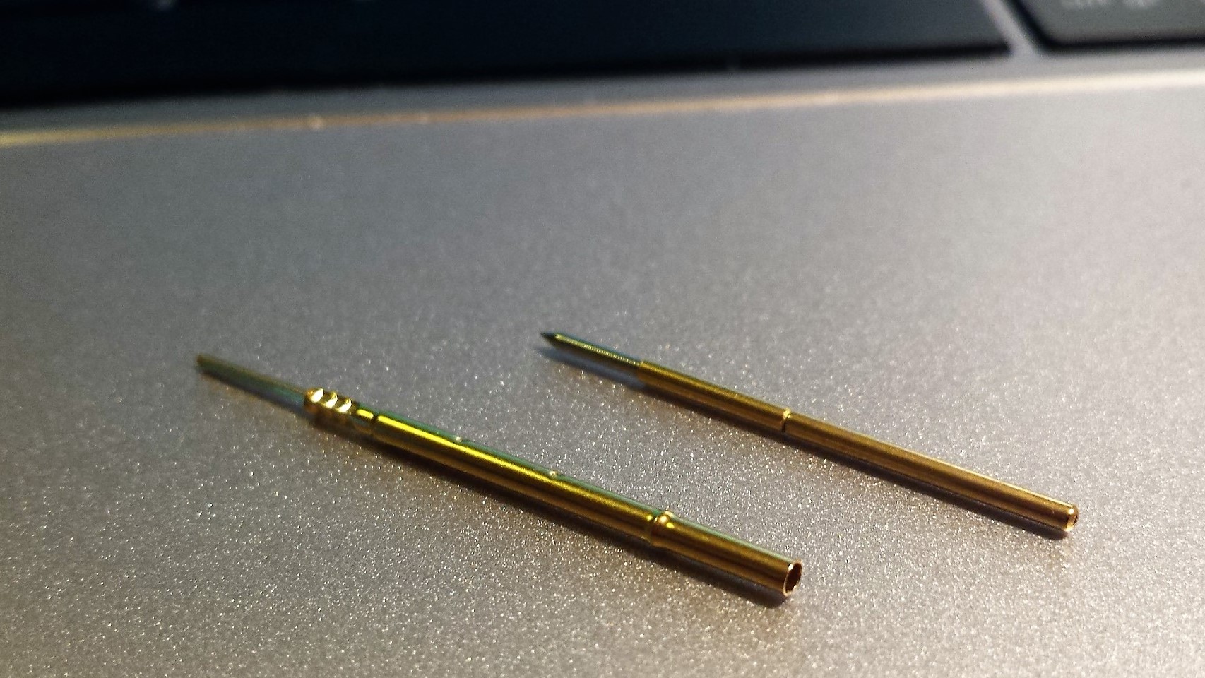
In most DIY projects where pogo pins are used people solder them directly to a wire or pad on a PCB. Despite it looks like it is the way to go, it isn’t. Pogo pins tend to wear out relative quickly as they are only rated for a couple of hundred ‘compressions’, also solder can sip into the pin and ruin its spring. The proper way is to use matched sockets, which allows quickly replacing wore down pogo pins. They come in two variations: wirewrap (or PTH) and directly solder able. The socket has a also a ‘bulge’ to keep it secure in place.
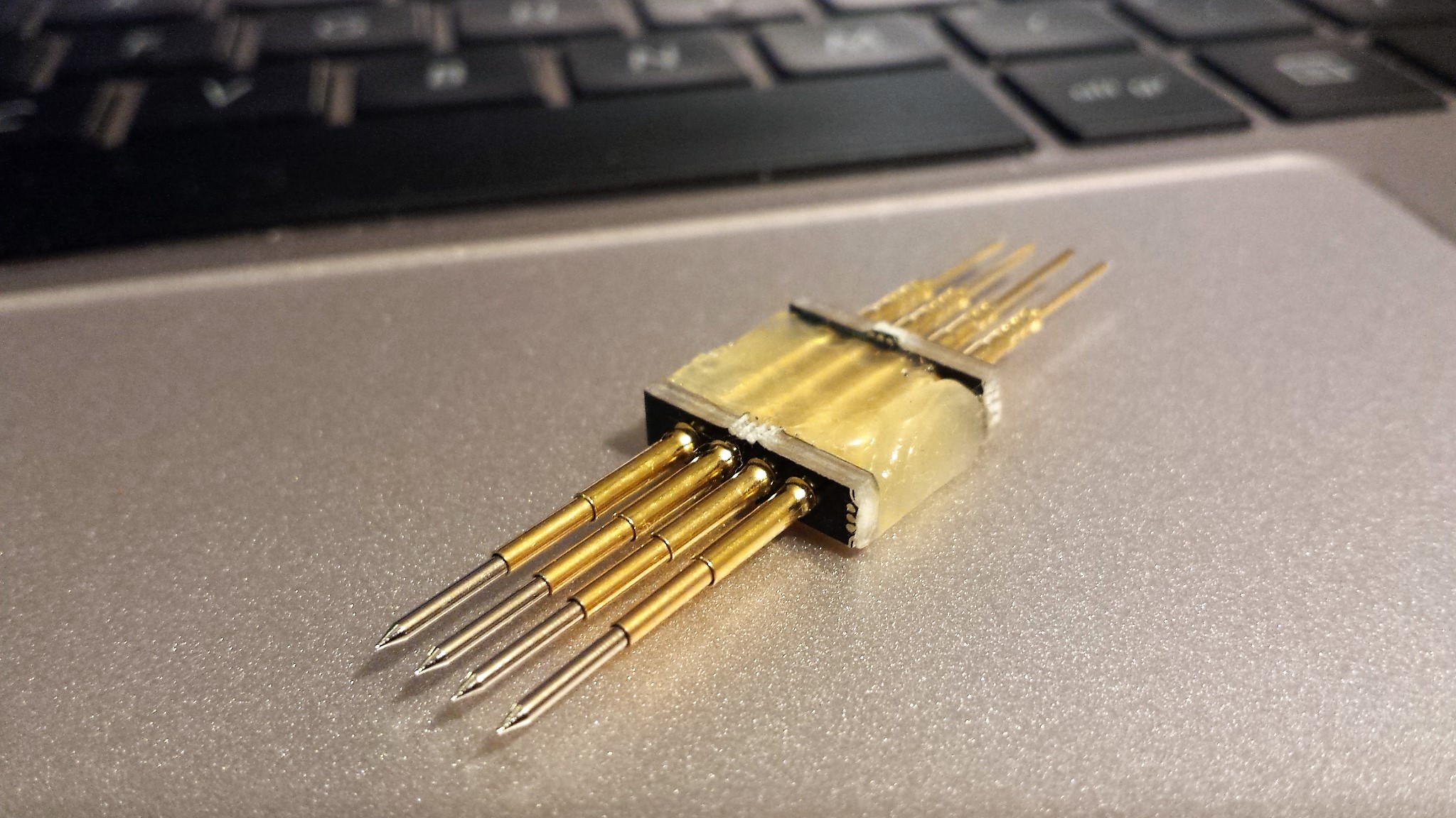
By using the excess PCB estate I created some common ICSP/debug arrangements: 2×5 (JTAG), 1×5 (Microchip ICSP) and 1×4 (serial, SWD). The holes have a diameter of 1.7mm, which is a bit thicker then the pin diameter, but smaller then the bulge. The pogopin is fixed to the PCBs by blobs of hotglue. Optional some heatshrink tube can be applied.
I got my pins in directly from a manufacturer in Shenzhen but you can get them per 100 from here. Also the mechanical drawing are provided there.

Hi,
Can you please let me know where you bought those pins?( the manufacturer’s contact).
I thought about doing a test jig for CPU with about 26×26 pins.
Do you have any experience with such large jigs?
Thanks
I got them on one of my sourcing trips in Shenzhen. The manufacturer is located in SEG market, 3rd floor. Unfortunately I have no businesscard, but many stores there sell them.
I don’t have experience with building ZIF sockets for CPUs either, but if it is a common footprint you can find a ZIF socket on Aliexpress or Taobao easily. If no one has ask try contacting them for building one. Keep in mind some are asking fairly large MOQ (minimum order quantity). Alternatively go for the PCB adapter solution: http://smdprutser.nl/blog/ghetto-qfn32-zif-adaptor/ Perhaps you are more lucky then I am 😀
You can find lots of variants of these on taobao. It seems like it’s common to use two standard M3 standoffs to give the whole thing some rigidity. And then heatshrinkwrap the whole thing.
ex: https://world.taobao.com/item/529323749230.htm and https://world.taobao.com/item/531379691846.htm
this is a fancier version: https://world.taobao.com/item/43351335933.htm
I really like these for developing / debugging https://world.taobao.com/item/534058232548.htm they have the right amount of springy-ness. You can just clamp them on your test/debug port on the edge of your pcb and leave it connected.
Haven’t used these ‘chopstick probes’ yet, but they look interesting for debugging: https://world.taobao.com/item/547735307773.htm
This is a good search term btw: 編程 測試 夾子
I remember seeing those clamps in HQB. They are soo sweet.
Thanks for the links and translation!