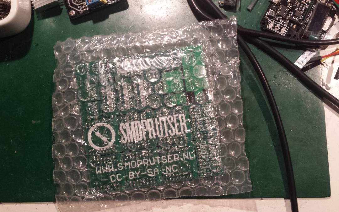
Every now and then I send off 3 to 4 gerbers to my friends at dirtypcbs.com. I really like them as they are really cheap (am I Dutch or what?) and they provide reasonable PCB’s. I don’t like to wait about 3 to 4 weeks for them to arrive so I use their DHL 3-5 days shipping option. That is relative expensive (about 25 USD), but PCBs don’t weight that much. Adding a couple more designs won’t add up too much to the shipping cost.
I did sent in the following gerbers:
- C64 RAM/ROM cartridge with integrated SD2IEC.
- 23C64A adapter.
- (Hopefully) Final design of breakable SMD protoboards.
- uC controlled dummy load.
Can’t tell much about the PCB’s yet as I first started to solder the C64 RAM/ROM cartridge. As always the PCBs look very promising and wellmade but I tend to be cutting some corners. As a result there are tons of stupid mistakes and a board usually takes a revision or two to become usable 🙂 I’ll will write a post about that in the near feature and how to circumvent that.
C64 RAM/ROM cartridge with integrated sd2iec
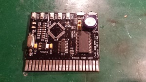
 Here is a sneak preview of the C64 cart, which has a 6264 SRAM chip and a Atmel 644 (or 1284). The SRAM can be programmed by the C64 and with the flip of a switch (actually 2) it becomes a standard 8K ROM cart. The Atmel part emulates a IEC floppy drive. I didn’t have the Atmel part yet at hand, but i soldered all the other components. I will do an update if the SD2IEC part is ready, for now the SRAM and the ‘cartridge’ emulation seems to work at first glance.
23C64A to EPROM adapter
From an old friend I got a vintage SX64 some time ago and decided it needed an upgrade with Jiffydos and SD2IEC. I like to keep the SX64 as original as possible. However I also like the silver thumbleswitches to choose the Kernal or cart. First I need to replace the kernal of the C64 and the 1541 part. Both are 23C64A EPROMs without a window. 23C64A EPROMS are hard to find nowadays so I made an adapter to a more common EPROM (as common as it get in these flash days). It can take a 27C64, 27C128, 27C256 or 27C512 EPROM. It has the upper address lines broken out to select the ROM bank.
Final design of breakable SMD protoboard
When trying out the protoboard and taking pictures of it I noticed I made some errors and got some of footprints wrong. I replaced all the resistors/capacitors/LEDs with an 0805 footprint (accepts 0603 too). Also I used a hard to hand solder micro usb connector so I ditched that in favor of a mini USB. I tried to fix some other stupid mistakes on the PSU and uSD breakout.
uC controlled dummy load
I always wanted to built my own powersupply, but to test it you need a dummy load. As a dummy load is easier to start with I started with that 🙂 I got inspired with the re:load and added my own sauce.


Trackbacks/Pingbacks