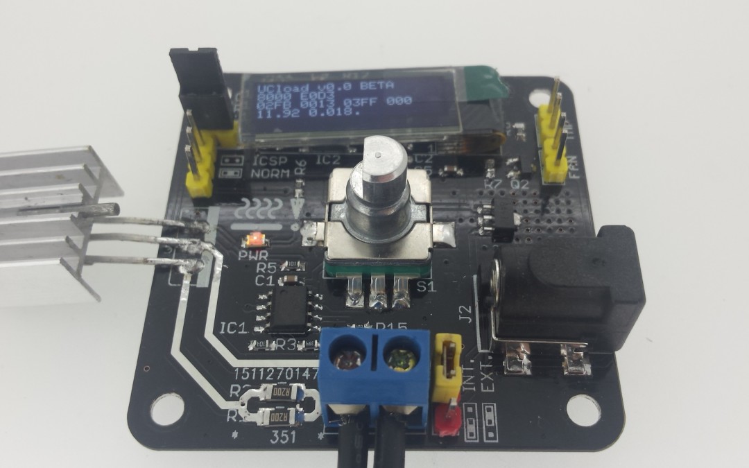
With no snow outside I finally got around to solder the 3rd PCB. It is the second revision of a microcontroller dummy load. It is loosely based on the arachnidlabs uc:load. It uses the same base ciruit and adds a microcontroller (PIC16F1825), rotary encode switch, external powersupply and offcourse a 128×32 OLED.
The picture shows a quick and dirty firmware I wrote. The top line states it is as BETA as it get, so no warranties there :). The second line displays the rotary counter and the 1ms ticks, the next the raw ADC values (Vin, Iin and Tamb) and the Iset setting. The last line displays the calculated Vin and Vout. The dot stated the rotary encoder isn’t pressed (a ! is displayed when pressed).
The FET is controlled through an opamp which compares the DAC from the microcontroller with the voltage across a 0.1 Ω shunt. The range is upto 1A (actually 1.024A), which is the range I was looking for. Using different resistors in the opamp stage could give other ranges. The FET is capable of voltages upto 30V, however the voltage divider used would limit it to 16V. My intendent use of this dummy load is to do basic measurement on some batteries I have lying around, and testing of the power supply I’m still designing (if ever finished).
The prototype does work but the firmware is far from finished, as far as I can see the hardware seems to be ok. A quick test with a DVM shows the current reading and voltage readings are within specs. I noticed some small silkscreen defects but does it require a new revision? Time will tell…

Nice work! It’s great to see people building on the Re:load design.
No problem!
I really liked the robustness of the FET you choose. Have been testing the whole day and it looks like a very solid design and working great. Next step is making the firmware a bit more user friendly 🙂
Looks great!
It would be nice not to use the tiny OLED something but a proper 1602 or 1604 LCD instead.
Also real binding posts would be great at least as an option.
Nevertheless, it is a nice and interesting project. Do you plan to publish design files & source code?
I really like the OLED over any character LCD anytime.. It is so much clearer and better readable then the LCD. If you use it purely as a character display (as shown in the picture) you can display 4 rows of 21 chars (5×7 font). But when you want to add a simple discharge curve it can be easily done, try that with a 1602 display 😉
Binding post will be nice, but wont fit the PCB. I kept it under 50x50mm as these PCBs are super cheap to manufacture.
As for the project files check its ‘product’ page under the products page: http://SMDprutser.nl/products Not yet finished (see the picture ;)) but will update it later on.
Many thanks for your answer.
Of course I do not want start a flame, but for me and other elderly people, it is pretty annoying to to change our glasses every time we need to read some instrument’s itty-bitty display. I consider small OLED displays inappropriate for anything intended to be placed on the desktop or instrument shelf. Maybe a wearable wrist-mounted electronic load would be a nice idea that could benefit from the small display size 🙂
As for those binding posts, I am not quite convinced that you can not squeeze them somewhere on a 50×50 board with a bit of effort. Maybe I will try my own iteration on your design, equipped with 12864 LCD and proper binding posts (and maybe smowhat wider (double sided, via stitched, tin soaked?) current path) after you publish the design files.
Best regards and happy new year!
Tomas