I finally found some time to check out the UCload project. A couple of weeks ago I quickly soldered the PCB and wrote a quick’n’dirty firmware for it. The basic functionality was working, but it wouldn’t do good for the shiny display.
Today I locked myself in my mancave and shut myself off from the world. Turned the light down, pulled loud music from the speakers and started coding like hell!! Not exactly but I found some time to write some more decent firmware for this load. In a previous revision of the PCB I forget the pull up resistors and swapped the SDA and SCL signals. I corrected that and made some small other changes (still ****ed up the silkscreen) in revision 2. The hardware is quite OK and rock solid (prolly more due to the robust FET then my analogue skills :)). However I managed to use a 1n4148 diode to measure the temperature. Connect it to the heat sink and if that one gets to hot turn on a fan. It accuracy is terrible but capable of detecting over temperature 🙂
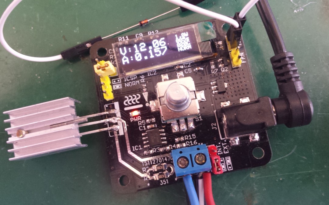
On the left part of the screen it will display the voltage across and the current through the load. On the right side it displays/calculates the dissipated wattage, elapsed time, temperature of the heatsink and mode.
I tried to implement a graphical view of things (voltage or current) too but don’t think the display will display all the details. I can scale the voltage (ADC provides 10 bits) down to 5 bits (32 pixels) but the details (small fluctuations) wont show up. Using the last 5bits gives the details but you wont see the big picture.. Difficult choice.
Future enhancements would be a constant current load for batteries, counting the seconds it will last until the voltage drops under a certain voltage or a pulsing load for testing powersupplies.
