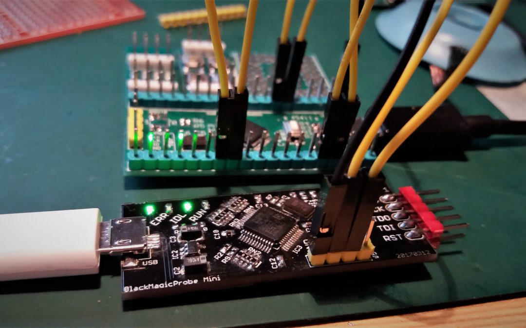
Since the GD32F103 can run as fast as 108MHz but has not a proper USB clock divider to provide a 48MHz clock for USB communication we need another way to communicate with the outside world. Since the early days of computing the easiest way to go is a asynchronous serial interface using the UART peripheral. I can try to explain how this protocol works, but here is a better write-up.
The test setup is quite simple, but uses all UART ports. Both chips have 3 UART peripherals which I put in series to form a daisy chain. To test if the peripherals work the code echoes each received byte back. If everything is ok the byte is echoed back to the console. I used the onboard usb-serial port provided on the blackmagic probe to check if everything gets across. (In)fortunately it works as expected and both chips worked fine. Both chips generated a bittime of 8.7us which is spot on. I gonna use the UART peripheral in the next challenges for debugging and status reporting.
The reason of the USB clock divder f*ckup is probably they expected that the silicon is able to run with a clock of 120MHz, as there is a divider of 2.5 present. I’m planning to do some overclocking as (one of) the last episodes in this series. Don’t have any experience in this field so help is welcome. As I found a reliable source of GD32 chip I’m planning to spin a small run of development boards (the same as used in this series), the expected price will be around the 10 EUR mark. If interested please leave comment or use the contact us page.
As always the code is found on my GitHub page.
This post is part of a series where the STM32 is compared to the GD32:
- Part 1: Solderability
- Part 2: Blink a led
- Part 3: UART
- Part 4: SPI Master


Hi Sjaak,
does your source also have the QFN version? I would need this chip as replacement for my quadcopter flight controllers: GD32F130G6 (32 kB) or G8 (64 kB).
I send you an email 🙂
Just clock it at 96Mhz and use /2?
Then it is not running at 108MHz..
I want to do all tests at the chip maximum clockspeeds; for the USB subsystem the 96Mhz will be the maximum for the GD32, but will try it at 120Mhz.
The USB clock divider is not F*ed up. Or, at least, not any worse than other SOCs. Quite a few SOCs cannot use their USB peripheral when their clock source is set to maximum.
I think it is as it has a PLL/2.5 setting which makes no sense when 120MHz (2.5*48) is not supported.
Have you tried testing if there’s a measurable startup delay on the GD32? I’m also curious how devices with more than 128K flash behave when you cross the threshold, and how they’ve implemented the code mirroring. If you eg. have a loop that straddles a 128K boundary, will it constantly reload each block? Also, what happens if you write into code space, does it behave like flash or RAM?
Good idea. Will do this later on.
Hi Sjuak
I’m tring to migrate STM32F103RB to GD due to supply instability. Have you ever experienced output delay in USART function between both IC’s ? This is because GD has some delay time between data frames in the Tx mode even with the same system clock such as 72MHz. I want to know the cause. I’d like to get some help. The related screenshots are ready, but I’m sorry I can’t put it here. If you are interested, please let me know your email address and I will send it to you. Thank you !
Unfortunately not.
I’ve read somewhere the GD fetches flashcode into dedicated ram from where it is executed (kind like the ESP chips work). Perhaps this gives a delay?
Is it a fixed delay or more random?