I played some time with the idea of making a cheap testing/programming jig. For the T12 controller I had one professionally made in Shenzhen. It wasn’t too expensive but IIRC it was about 65-75 USD and came without any wiring. Testing jigs are basically a fixture for the assembled PCB and some pogo pins that connects to the programming and/or test pads on that PCB. Those pins are connected to a programmer, power supply or sometimes to buttons and LEDs. Basic rule is to keep it as simple as possible and the number of connections to a minimum.
Inspired by an old article from sparkfun and some tests I conducted myself I came up with a PCB that holds the pogopinholders and an lasercut acrylic fixture for the PCB on top. Using the dirt(y)cheap services from dirtypcbs.com the cost for this jig, including pogopins and their holders is about 45 USD. As an advantage you receive 5 lasercut acrylic and 10 PCBS which allows you to make 3-4 jigs in total!
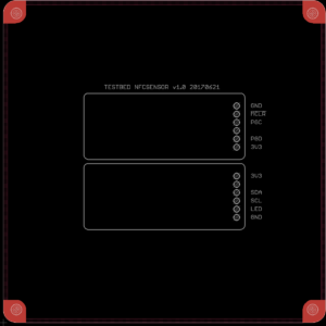
To design the PCB that holds the pogopins I started with a 10×10 PCB with M3 mounting holes and imported the to be programmed PCB (File, Import, Eagle drawing) and place this in the centre (not mandatory, but looks prettier). Next I used a 1.7mm drill (which is the diameter of the pogopinholder) to mark the spots where the testpoints are located. After this everything of the to be programmed PCB is removed except the outline, which is later on converted to the silkscreen (tPlace layer). As a bonus I added the signal names to the PCB (which make it easier to hook up the programmer or test equipment later on). This PCB is converted to gerber the usual way and send in.
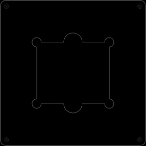
The lasercut acrylic is based on the previous created PCB. Everyhting is removed except the outline of the outer and innerboard and holes. Next partial circles are added to easily place the board. Before exporting the file to DXF format (File, Export, DXF) make sure only the layers are visible that needed to be cut. Also make sure there is a bit of extra room to easily place the PCB and account for laser tolerances.
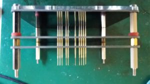
To finish the rig the the layers are stacked and held together bij hexagonal standoffs. I had to use some washers as I didn’t have the right spacers. Lets say functionality rules over esthetics for testingrigs 😉
Note I used Eagle 7.5 for generating the gerbers and DXF files.


What’s your source and cost on the pogo pins?
I get mine from dirtypcbs and they are about 10USD per 100 pins ( http://dirtypcbs.com/store/designer/details/ian/12/dirty-pogo-pins ). They stock all the different variants and have a nice datasheet which one to use for a particular connections: http://dirtypcbs.com/uploads/store/pogo-pin-P100-series.png and http://dirtypcbs.com/uploads/store/pogo-pin-tips.jpg