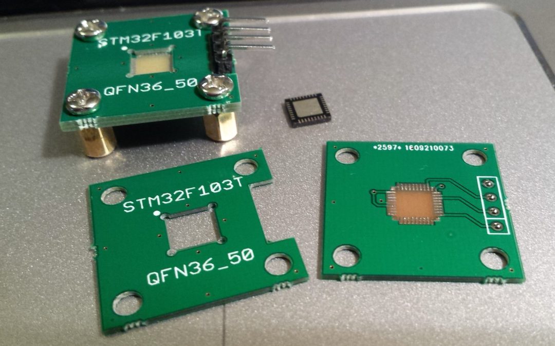
I’m always fascinated by Zero Insertation Force (ZIF) Sockets, but a bit scared by the price. Simple ones (DIP and SOIC) goes for a few bucks on Ebay, but the more fascinating ones (QFP, QFN, (T)SOP, BGA) either can’t be found or are very expensive. Even on the markets in Shenzhen they are 350 CNY. Remembering a post from Sparkfun about how they make their testing rigs and using the cheap PCB as construction material.
I wanted an programming socket for a QFN32 0.5mm pitch chip (STM32F103T) so I started with a footprint I used for the board itself and routed the powersupplies and programming signals to a .1″ header and connected the BOOT0/1 and !RST to their appropriate levels. Next on a different part of the PCB a 4x4cm cutout for the chip with holes on the corners; this should make it easier for the PCB manufacture the cutout. As a last step added 4 holes for screws to bolt things down and align the PCB.
As expected getting the cutout to position the chip accurate is a pain in the ass and the pcb substrate is getting really loose in no-time. I never really got a good reliable connection, let alone I successfully flashed a microcontroller with it. Probably with larger pitch IC it can work out, but this is why I guess professional ZIF sockets costs 50+ USD 😀


Did you push the QFN chip down (applying some moderate force with a finger) while trying to program it? How about removing the pads from the QFN footprint which are not used to make the remaining ones “stand out” to give better contact on them?
Yes, I pushed it down with my finger. Sometimes it gets hot (short circuit as Vcc and GND are next to each other) or no connection.
The real solution would be smaller pads with enough spacing between them not to short them and some kind of plastic/soldermask between them so the chip would align itself. My guess is also that 0.5mm is too small for this setup 😀
Was a fun experiment with some spare PCB estate.
Thougt about putting a 3rd layer of PCB to push the chip donw by the screws?
Yes, but height of the chip is about 0.8mm (the same as the PCB thickness) so I pressed it down. The problem is the pads of the qfn falls between the pads on the PCB. At best they make contact with the right pins 🙂 Perhaps a center pad would make a difference.
Perhaps I do another revision 😀
I would have liked to see a bit higher resolution of this nice hack.
Some thoughts for the next iteration:
1). Make the pads on the pcb narrower then the spacing between the pads on the QFN to prevent shorts.
2). Remove most of the unused pads on the PCB to put more pressure on the pads you need for Vcc / GND / Programming.
3). But leave some pads on all sides to prevent the QFN from slanting.
4). Put a hole in the middle, add a spring / piece of foam to push the QFN out.
5). Add some decoupling caps.
6). Screw it on a piece of wood & add a toggle clamp.
https://www.aliexpress.com/wholesale?SearchText=toggle+clamp
Thank you for the tips.
Those toggle clamps are too big (at least the ones I saw in the HQB market) for this tiny chip 😉
I think most problems will be solved with soldermask or a filler as that will level with the copper pads. Now the pads of the chip are of falling between two pads and thus shorting everything.
Which part of the toggle clamps is to big?
I suggested mounting the whole thing on a piece of wood to have some place to screw the clamp down.
They also have a replacable rubber foot which can be cut to size or completely replaced by anything you want.
But I think the rigid pcb with the footprint is never going to work reliably.
You could have the pads milled out on long trapezoidal “fingers” to add some flexibilitly, but today I probably had an even better idea.
Filling with soldermask probably won’t help much. I’d search for a solution in better / tight alignment.
You can put the footprint on gold plated flex. and add some flexible material (foam?) underneath to press each individual contact to your QFN. The pcb manufacturer below seems to have reasonable prices for flex.
https://www.multi-circuit-boards.eu
This looks like a fun project, but I do not have use for ZIF sockets myself. I just add a programming header to my boards.
The chip is 5x5mm so almost all is too large 🙂
The whole point of this adaptor was for programming a small batch and the fun of learning, not for reliability. ZIF sockets aren’t cheap, but are worth their price. I mostly use programming header/pads for programming/testing.
I think flex will break/fold when using it for more then a couple of chip. Love to see someone trying it though 🙂
The flex was not supposed to bend more then a few degrees.
Another Idea:
SMD footprint on gold plated pcb.
Add some Zebra Strips.
Press IC in Zebra Strips.
After 100 cycles:
Replace Zebra Strips.