
The defacto ‘hello world’ for microcontrollers is blink a LED at a steady rate. This is exactly what I’m going to do today. I made a small 5×5 development board, soldered it up and started programming. In this first example we not gonna use fancy IRQs or timers to blink at a steady rate, but we insert NOPsas delay. This would give an idea of the RAW performance of the chip. The used code is simple; set up the maximum available clock available and then toggle RA0 for ever.
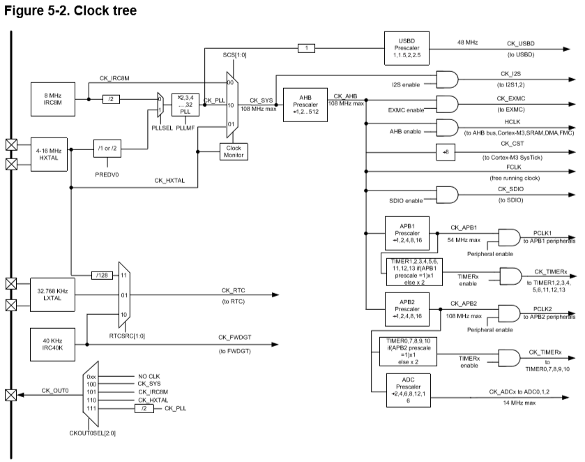
8 Bit microcontrollers usually use setting of a single config word to run at a certain speed, but an ARM has multiple clock and PLLs running for the core and all the peripherals to work. There are several clocks needed to run at different speeds. My usual route is to use a clock setup provided by the library I use (libopencm3.org) but the GD32 can run faster so I need to provide my own. Looking at the diagram above made my head spin a little, but finally I got it. The GD32 is running at 108MHz and the STM32 at 72MHz.
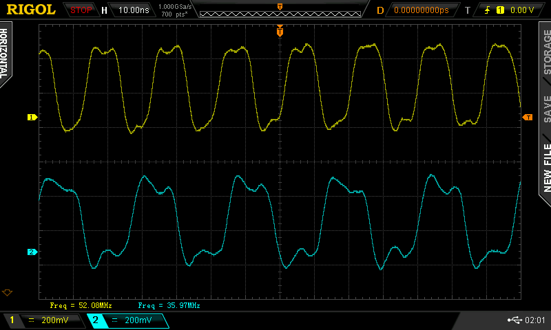
To know if the chip is running at the desired speed, I used the MCO function which outputs internal clock (8Mhz RC clock), external clock (I used a 8MHz crystal here) or the PLL divided by 2 (which is 36MHz for the STM and 54MHz for the GD) on pin PA8. Officially the output may not exceed 50MHz but the GD clocked out at 52MHz (which is I think caused by my scope and bandwidth limiiaton on the chip itself).
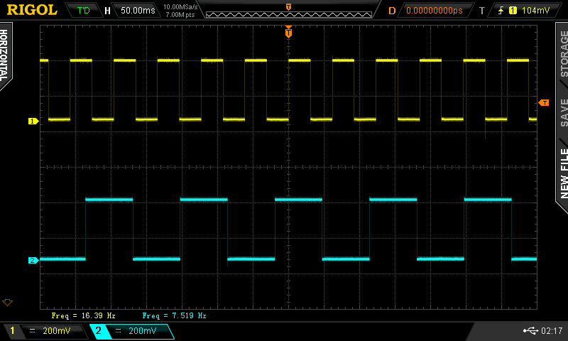
This screenshot of PA0 shows the blinking is a bit more then twice a fast. This can be explained as the chip is running 150% faster and the access to the flash has no waitstates. For 72MHz the STM needs to insert 2 waitstates for every flashaccess, so reading data from flash would take 3 clockcycles on STM and 1 on GD. The next screenshot show the pulse rate when both are running 72Mhz (The GD seems to ignore the waitstate settings although the reference manual mention it I available):
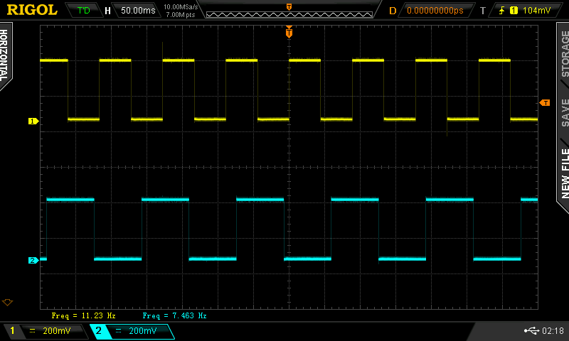
Both chips running at 72MHz. Since the GD chip seems to ignore the waitstate settings this could be a simple check the genuinity of stm chips on ebay or aliexpress?
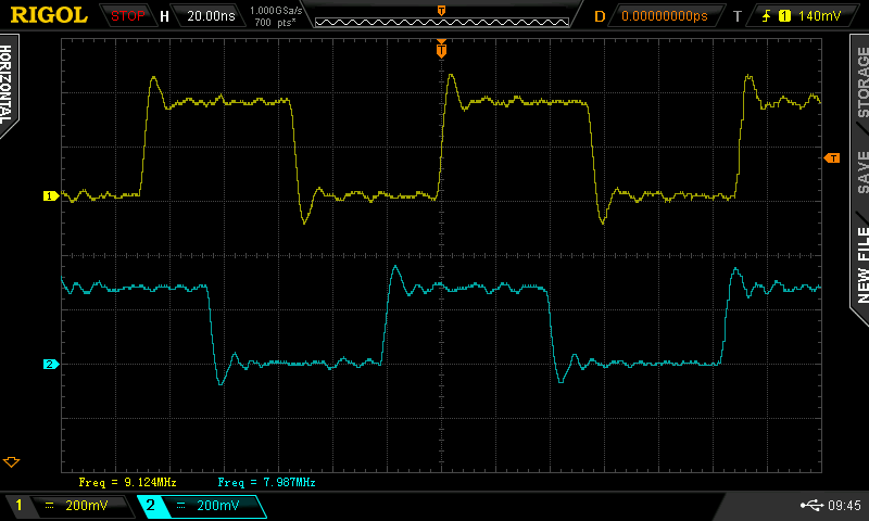
Studying a bit more on the clocking it revealed the internal clock of the GD32 is 9MHz. I can’t confirm all the GD chips have a bad internal clock as I’m still waiting on some to arrive. It can be because I needed to reset the configuration words as the chip came write protected. I couldn’t find any info where the calibration are stored, but the reference manual states the calibrationdata is loaded on reset (page 86 of reference manual 2.0). More tests when the new chip arrive. To remove the protection these commands can be used on the BMP:
$ arm-none-eabi-gdb
(gdb) target extended-remote /dev/ttyACM0
{gdb) monitor swdp_scan
(gdb) attach 1
(gdb) monitor option erase
(gdb) quit
All code can be found on GitHub. Go to the source/blink directory and use ‘make STM=1’ (compiles the STM version) or ‘make GD=1’ (GD32 version). Be sure to do a ‘make clean’ in between.
This post is part of a series where the STM32 is compared to the GD32:
- Part 1: Solderability
- Part 2: Blink a led
- Part 3: UART
- Part 4: SPI Master

The picture of the clock layout seems to be for the STM32, it says that SYSCLK has a max of 72Mhz. The manual of the GD32 states the actual 108MHz (CK_SYS). I downloaded the document from : http://gd32mcu.21ic.com/en/index
the picture was indeed of the stm32. I found it more appealing, but I changed it since it is a bit confusing. Thank for catching that one.
Hi .
Very interesting work.
I am new to the GD range of chips , we have the GS32f105 RBT6 and the GD32F405RGT6 ,
We can pgm both with a ST-Link via SWD , that works but the code does not run .
At the moment we tried just very basic port pins toggle and a line or 2 serial output , the same code runs fine on the ST32F105 and or ST32F405 chips .
The crystal is running at 8 and 12 MHz on the 2 chips – scope checked.
We are missing something important but not sure what to change to get the chip to respond.
Can you maybe share a hex file with the very basic for a GD32F105 to toggle ports c13 – c15
for testing . Then at least we know the chip is running .
Any other help to get he chips working ?
Kind regards
Nico
I think those ports only can do weak pushpull as they are involved in the 32khz realtime clockpart of the chip. there is somewhere a note about those pins